EE40 Summer '04, Lab8
Notation for this lab:
pi is the greek pi (whose value is 3.1415.....)
w is what we called omega in class (the angular frequency) and is equal to 2*pi*f where f is the frequency
j is the imaginary unit
sqrt(x) is the square root of x
x^b means x to the power of b
|x| means absolute value of x. If x is a complex number x=a + jb then |x| = sqrt(a^2 + b^2)
Introduction
This lab focuses on diodes. You will built an AND gate in negative logic and a voltage tripler. The AND gate schematics is depicted in figure 1.
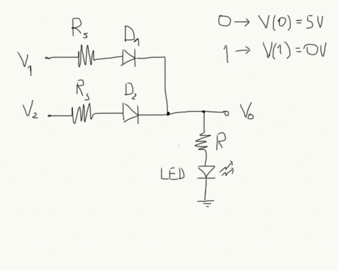 Figure 1
 You will use a LED (light emitting diode) to verify that the output is 0 or 1. An LED emits light when it is on.
Remember that the logic is negative meaning that the voltage representing 0 is higher than the voltage representing 1.
Answer Q1 of the pre-lab.
Now you have to set the values of the resistors.
We want the output to be 1 (0 V) only is both inputs are 0. If at least one of the input is 0 (5 V) then the output should be 0 (almost 5 V). When the output is 0 we want a current of 20mA to flow through the LED. We can consider Rs to be very small (10 Ohm) and V_{gamma} for all diodes to be 0.7 V.
Answer Q2 in the pre-lab.
Answer Q3 in the pre-lab.
Now you are going to build a voltage tripler (look at the lecture notes where you will find the analysis for this circuit). The schematics is shown in figure 2.
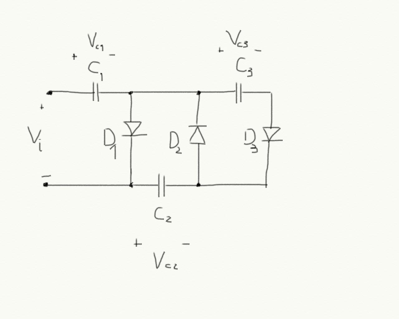 Figure 2
 First of all you have to analyze the circuit. Figure 3 shows the simulation result for C1=C2=C3=200uF.
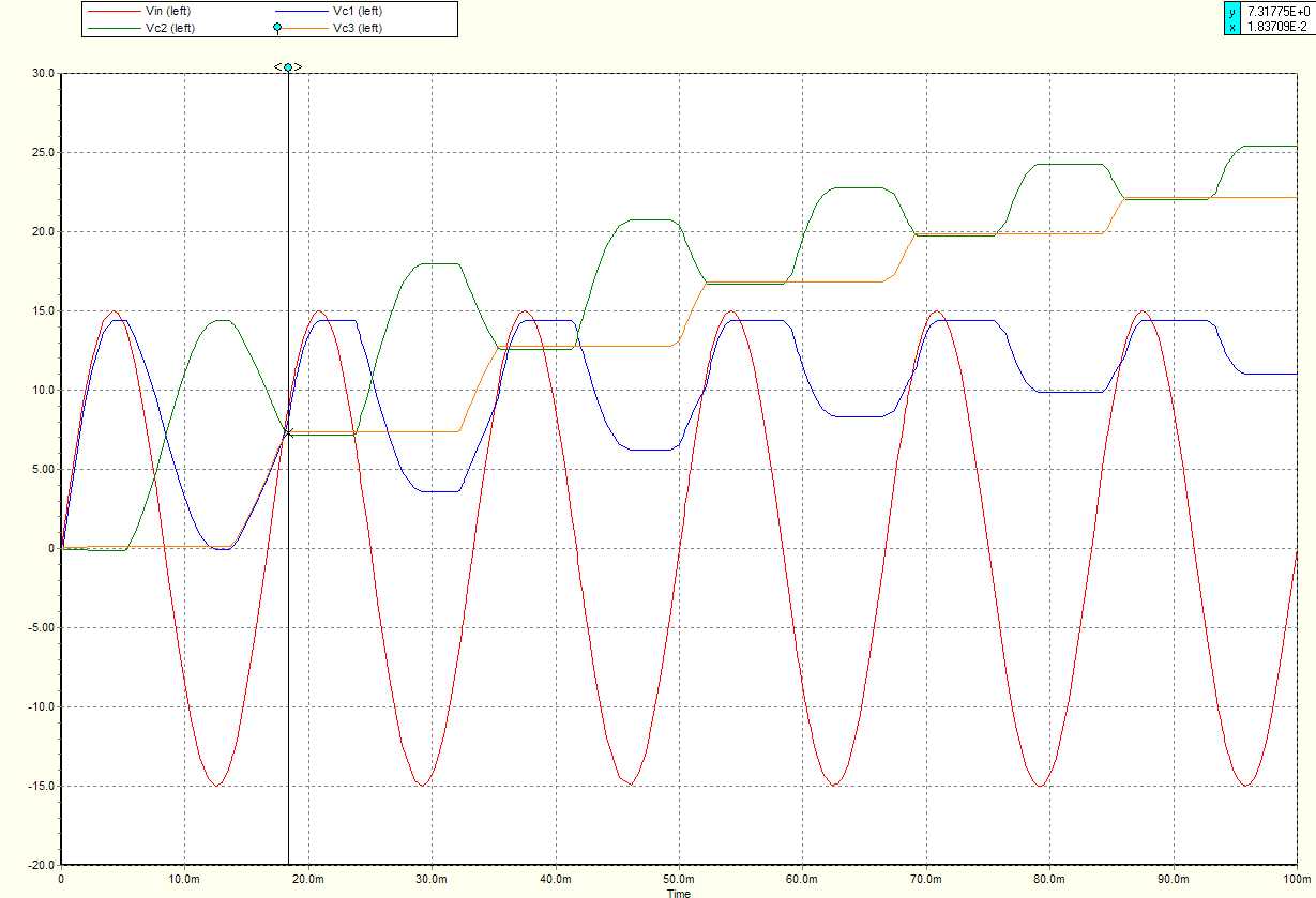 Figure 3
 Answer Q4 of the pre-lab.
The output is Vc1 + Vc3 (you should be able to connect your output pins at right points in the circuit).
Pre-lab
Q1) Write the truth table for an AND gate. You need three columns: input1, input2 and output. Write another column with the state of LED. For which combination of the inputs do you expect the LED to emit light?
Q2) Considering V1 = V(0) and V2=0 compute the value of R in order to have a current of 20mA through the LED.
Q3) Does the current in the LED change if both V1 and V2 are equal to V(0)?
Q4) Considering Vin = A sin(wt), verify that in the point indicated by the vertical cursor of figure 3, Vc2 = Vc3 = A/2.
Lab
In this lab you have to build the circuits that you have analysed. For all circuits, please check the diodes polarity before connecting the voltage sources. Make sure that your math it correct because if the resistors are too small, the diodes' current will be very high and they will break. I don't really know what kind of diodes you have in the lab. I think that they are 1N4002, here (.pdf) is the data sheet.
Even if you don't find the exact values for the resistor, try to use what is available in the lab (there are so many tricks you can do like connecting more than one resistor in series or in parallel, approximating formulas etc.).
Build the AND gate and verify that it works.
Now build the voltage tripler and verify that is works
. For this circuit you need an input voltage which is greater that 2*V_{gamma}. Set the function generator output amplitude to something like 5V. Use pretty big capacitor, try with different values and observe the difference. Try at list two values for C.
Report
As usual you should describe your experiment:
- What is the experiment setting: components used, their values etc.
- what are the stimuli that you are using: this also includes a description of the experiments that you are planning to do in order to claim that your circuit works!
- what is the result that you are getting
- What are the conclusions
Q1) You have tried two different capacitance values. Are the results different? Explain why.