EE40 Summer '04, Lab7
Notation for this lab:
pi is the greek pi (whose value is 3.1415.....)
w is what we called omega in class (the angular frequency) and is equal to 2*pi*f where f is the frequency
j is the imaginary unit
sqrt(x) is the square root of x
x^b means x to the power of b
|x| means absolute value of x. If x is a complex number x=a + jb then |x| = sqrt(a^2 + b^2)
Introduction
In this lab you will build a complete tone controller. We start again from the idea of summing the output of a low pass filter and an high pass filter as shown in figure 1.
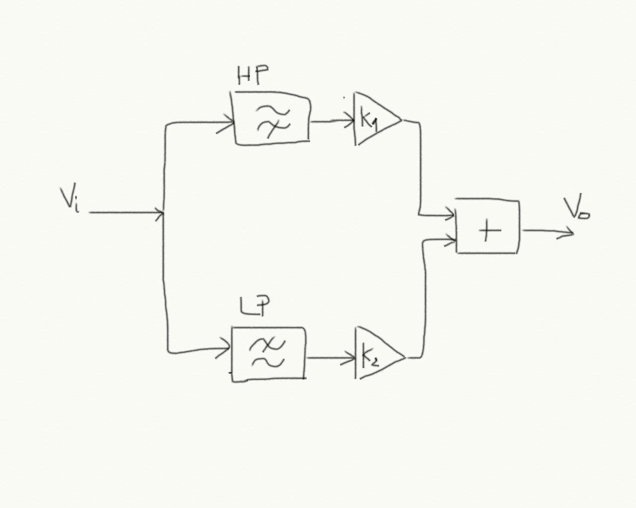 Figure 1
 We now have to put together the three basic blocks: LP, HP and the summing amplifier.
First of all we consider the cascade connection of a filter and a simple inverting amplifier like in figure 2.
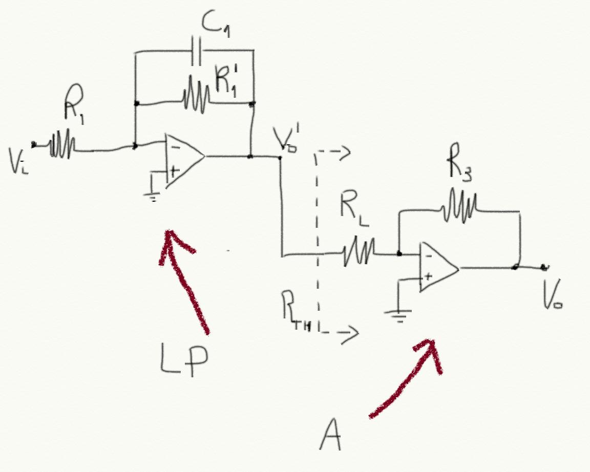 Figure 2
 First of all, analyze the low pass amplifier as if it was not connected to the amplifier. Consider R1=R1' and computer its cutoff frequency (the answer should be f1=1/(2*pi*R1*C). You can use the Laplace transform to do it, just computer the impedance of the parallel of R1 and C1 and consider it as a resistor whose value is equal to the impedance. Compute then the transfer function F(jw) = Vo'/Vin. Solve the equation |F(jw)| = 1/sqrt(2) to find the cutoff frequency (this should be pretty standard but if you have trouble doing it please send me an e-mail).
Don't go ahead if you did not answer Q1 of the pre-lab.
Good! Great job!
Now the problem is that when we connect the amplifier to the output of the low pass filter, the cutoff frequency is going to change. To see this effect, compute the Thevenin equivalent resistance at the input of the amplifier. You should be albe to do this using the following procedure. Consider the amplifier alone with nothing connected to its input. Now connect a test source Vt at the input an compute the current It flowing through the test source. The ratio Vt/It is the Thevenin resistance (the result should be Rl).
A simplified view of the cascade connection is shown in figure 3.
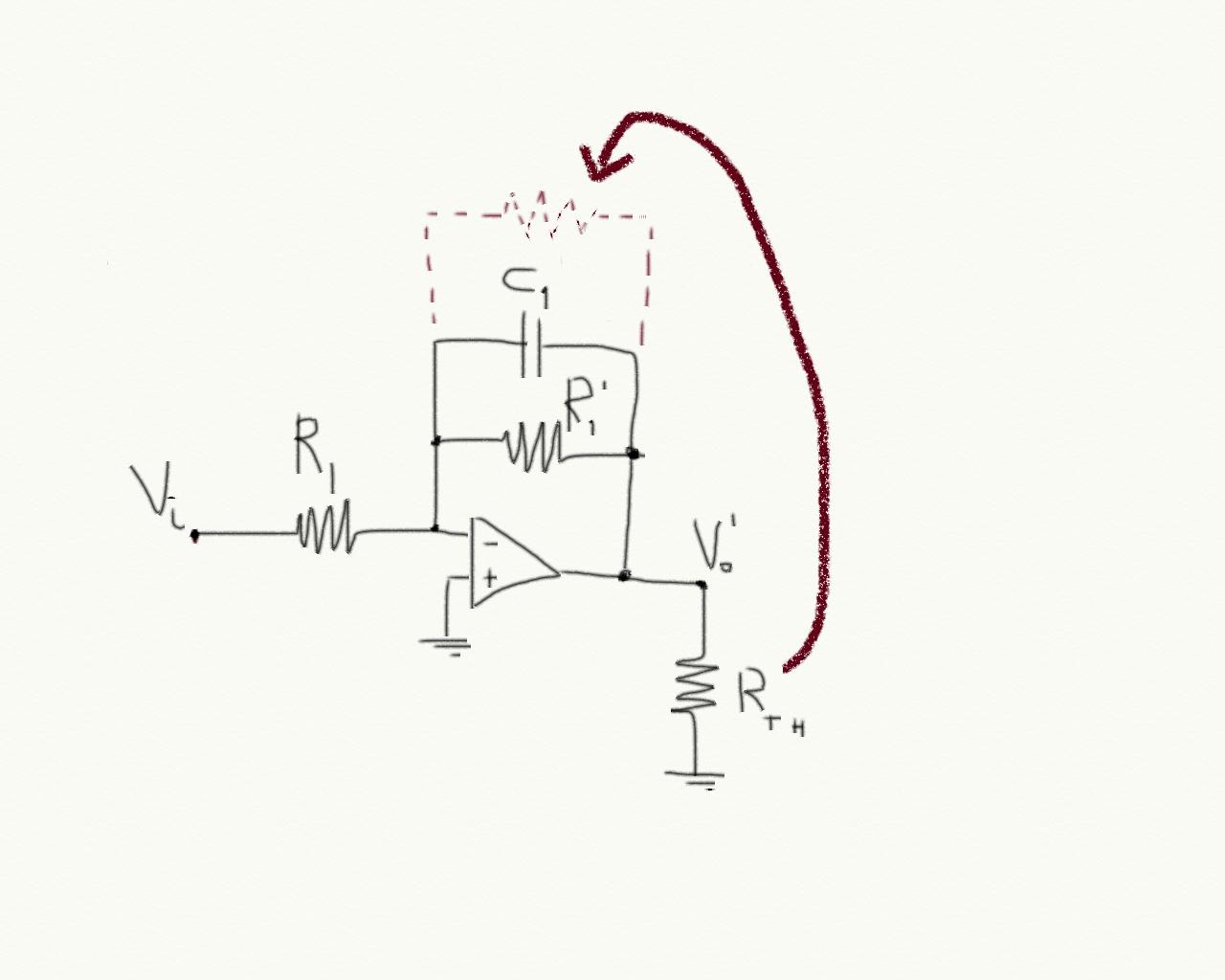 Figure 3
 The Thevenin resistor (which represents the input resistor of the amplifier) ends up in parallel to the capacitor because it is connected between the output and the ground exactly like C1.
Now answer question Q2 and Q3 of the pre-lab.
For the high pass filter, the circuit that we consider is like the one shown in figure 4.
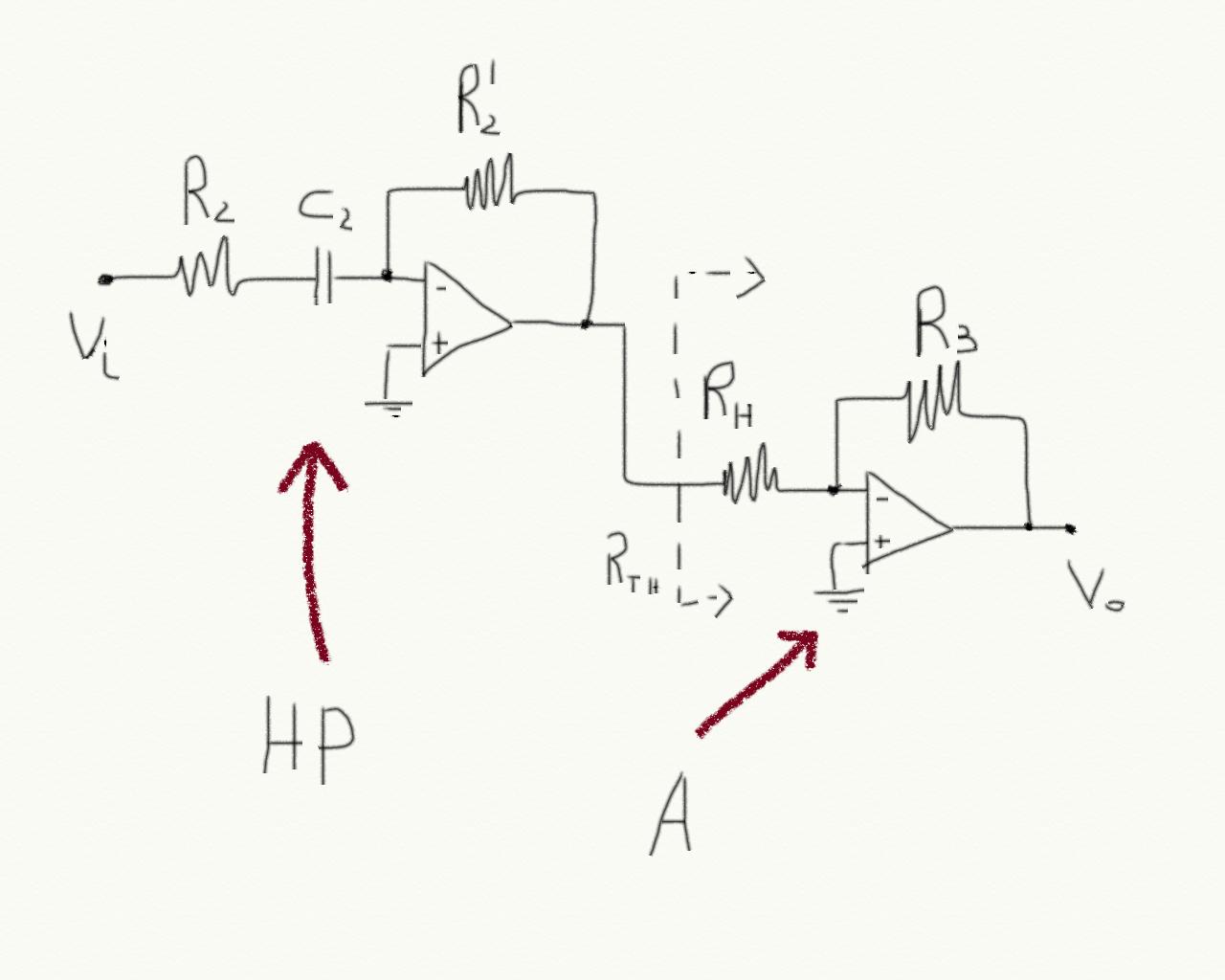 Figure 4
 Now you know how to take into account the effect of the input resistance of the amplifier on the filter. Answer question Q4 of pre-lab then!
Now let's put everything together to build our tone control. The complete circuit is shown in figure 5. Seems complicated but you know how it works!
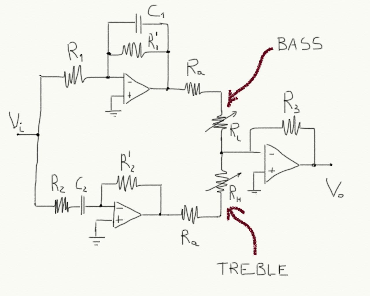 Figure 5
 The input is filtered by a low pass and an high pass filter. The filters outputs are fed into a summing amplifier. By varying Rl and Rh we can mix high frequency and low frequency.
We now have to compute values for all components.
Rl and Rh are two pots whose values can go from 0 to a maximum (that for the pots we have is 10K). Now we hare going to give some constraints on the components values in order to complete our design. Let's focus on the upper branch first (the low pass filter):
-
If Rl = 0, then the filter sees
and equivalent resistor (the input resistor of the summing amplifier) equal to Ra.
Of course we want Ra >> R1 (this should
come from the answer to Q3).
- When Rl=0 we want the output of the low pass filter to appear at the output of the summing amplifier without amplification or attenuation, hence R3/Ra = 1;
- When Rl=10K (which is the maximum) we want the output amplification (it is actually and attenuation) to be 0.3, meaning R3/(Ra + 10K) = 0.3
Congratulations! You have designed a tone control!
Before the lab I will post my numbers as a reference but please try to do the pre-lab and get used to approximations etc.
Pre-lab
Q1) Compute the cutoff frequency of the low pass filter of figure 1 considering it disconnected form the amplifier.
Q2) Compute the cutoff frequency of the low pass filter when it is connected to the amplifier.
Q3) What can you say about the value of the input resistance of the amplifier in order for the cutoff frequency to remain almost unchanged?
Q4) Apply the same reasoning you did for the low pass filter to the high pass filter.
Q5) Compute Ra, R3, R1, C1, R2, C2 by fixing the two cutoff frequencies equal to 5KHz
Lab
You have to build the circuit and then verify that when both pots are set to 0 the frequency response if flat.
Verify that when one of the two pot is set to its maximum value, the frequency response has either the low frequencies or the high frequencies attenuated (depending on which of the two pots you set to max).
Report
As usual you should describe your experiment:
- What is the experiment setting: components used, their values etc.
- what are the stimuli that you are using: this also includes a description of the experiments that you are planning to do in order to claim that your circuit works!
- what is the result that you are getting
- What are the conclusions
Q6) Is the frequency response flat for both pots equal to zero?
Q7) If it is, why? If it is not explain why and also explain what changes would you do in order to make it flat.