EE40 Summer '04, Lab14
Introduction
In this lab you will measure the propagation delay of an inverter. Important timing parameters associated with the speed of digital logic gates are the propagation delay time tPD, and the output signal rise and fall times, tR and tF. Propagation delay is a measure of how much time is required for a signal to change state. It is measured as the time from the 50% point of the input to the 50% point of the output (Figure 1). It is often cited as the average of the high-to-low and low-to-high delays (corresponding to the two transitions). The rise and fall times represent the amount of time for a signal to change state. To measure rise and fall times, you should be using the 10% to the 90% point, or vice versa.
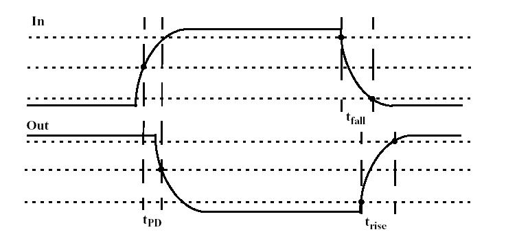
Figure 1
You can measure all these parameters by using a function generator and connecting two inverters in series.
A common way used to measure propagation delay is to build a ring oscillator like in figure 2.
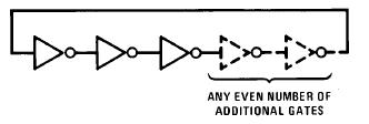
Figure 2
The voltage in this circuit is an (almost) square wave. By measuring the frequency of the oscillation and dividing by the number of inverters, we can get the propagation delay.
Pre-lab
No pre-lab is required. I basically did the pre-lab
Lab
First, measure the timing properties of an inverter. You should measure propagation delay, rise and fall time as defined in figure 1. In order to do this, connect two inverters in series and use the function generator as input like in figure 3.
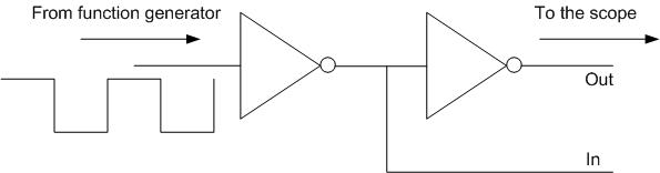
Figure 3
Using the scope, measure propagation time, rise and fall time between the two signals In and Out.
Now build a ring oscillator like in figure 2 and measure the oscillation frequency.
Report
Write the usual summary of your experiments and answer to the following questions.
Q1) explain why the ring circuit generates oscillation
Q2) is the propagation delay the same for the two experiment?
Q3) if not, explain what could be the possible causes.