EE40 Summer '04, Lab10
Notation for this lab:
X_{a} means X subscript a
Introduction
In this lab you will build a power supply.
The general scheme looks like figure 1.
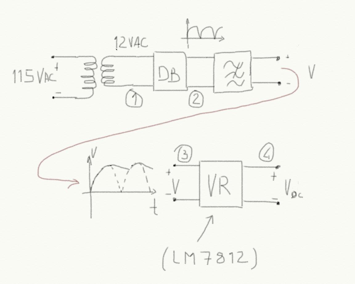 Figure 1
 The 115VAC coming out from the outlet is reduced by a transformer to 12VAC. You will use the transformer in your kit for this purpose whose output is 12VAC and a maximum current of 500mA. The output voltage is given as an RMS voltage. Starting from RMS voltage it is possible to obtain the peak voltage by just multiplying by 1.414, so the output peak voltage of your transformer is 12*1.141 = 16.968V.
Then a diode bridge is used to obtain a signal which is only positive. You have experimented a diode bridge in lab 9 so you should be pretty confident with this component now. The output of the diode bridge is also shown in figure 1.
Then we use a low pass filter (which is simply a capacitor in parallel to the output of the diodes bridge, to obtain an "almost" DC voltage. The residual oscillation is called RIPPLE. If there is no load connected to the output of the low pass filter, then the ripple is very small (almost zero) while if a load (a resistor) is connected to the output of the low pass filter then the ripple will increase because the capacitor will discharge on the resistor.
Finally there is a voltage regulator as final stage of our chain. This component makes the output voltage independent on the load (the appliance that we connect to the power supply). We will use a standard 3 pins integrated circuit for this purpose whose name is LM7812 and that you should have in your kit. The data sheet is here (.pdf). We also want an indicator saying that the power supply is on and we can use an LED for this purpose. The complete circuit diagram is shown in figure 2.
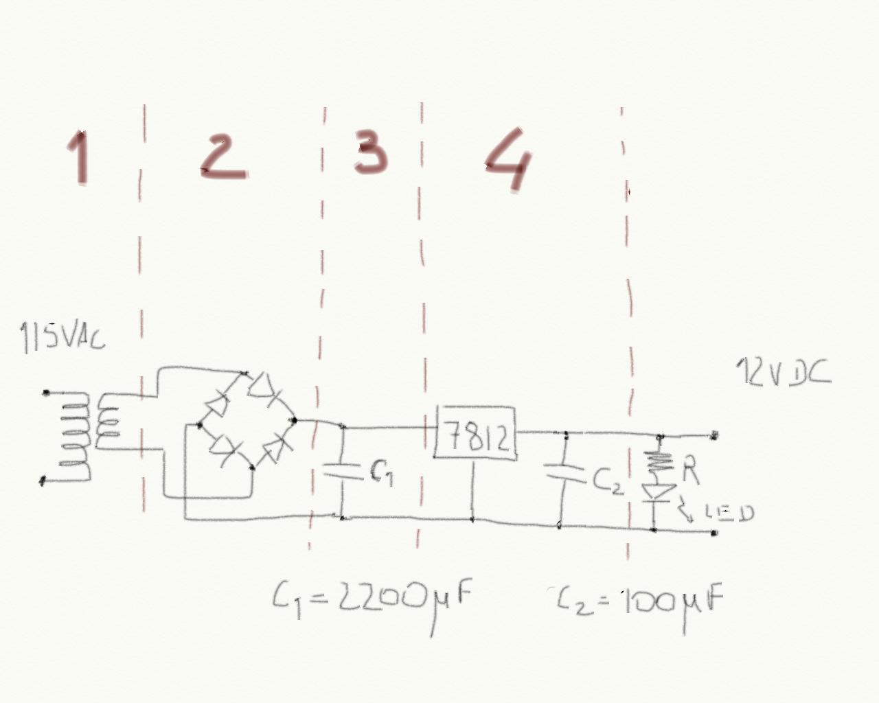 Figure 1
 R must be computed in order to have a current in the LED equal to 20mA. The circuit is pretty clear, please spend 10 minutes in reading the LM7812 data sheet in particular notice the parameter called Ripple Rejection which is the ratio between the input and output ripples.
Pre-lab
No pre-lab since there is a midterm coming up.
Lab
Build your circuit block by block. Blocks are numbered 1,2,3,4 in figure 2.
Build 1 first. Basically connect only the transformer to the outlet. Do not make the two wires touch each other. Before connecting the transformer to the outlet, place the two wires on the breadboard in such a way that they are not connected, then plug the transformer. Use the scope to measure the transformer output peak voltage.
Disconnect the transformer form the outlet but not from the breadboard. Now build the diodes bridge (2). Reconnect the transformer to the outlet and use the scope to verify the output of the diodes bridge. Go ahead only if the output is the expected one (notice that the peak voltage is reduced by 2*V_{gamma}).
Disconnect the transformer form the outlet but not from the breadboard. Build part (3), the low pass filter. Reconnect the transformer to the outlet. Now use the scope to measure the output. You can connect the LED and the resistor R to the output and see if the ripple changes (it should but I don't know how much it is going to be since the capacitor is pretty big, anyway measure it).
Disconnect the transformer form the outlet but not from the breadboard. Finally build the last part of the circuit including the LED. Reconnect the transformer to the outlet. Use the scope to observe the output and (if you can) the residual ripple.
Report
As usual you should describe your experiment:
- What is the experiment setting: components used, their values etc.
- what are the stimuli that you are using: this also includes a description of the experiments that you are planning to do in order to claim that your circuit works!
- what is the result that you are getting
- What are the conclusions
Q1) What is the maximum current that your power supply can ship to the load? Q2) Compute the minimum load that can be connected to the power supply.