EE192: Mechatronics Design Lab
Checkpoint 1 (draft 1-30-2018)
Checkoff Requirements
Print “Hello World” to terminal
Blink an external LED at 1 HZ using a Beaglebone Blue IO pin with 75% duty cycle
Introduction
This lab is designed to introduce you to the Beaglebone Blue and give you some basic practice with soldering.
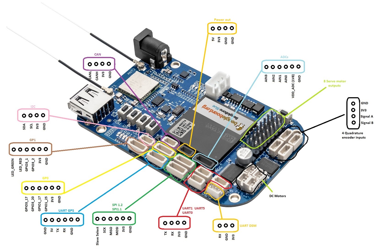
Useful documentation and pinout information can be found here:
To set up your Beaglebone Blue, follow the steps in our getting started guide here. You should do steps 2 and 5; steps 1, 3, and 4 have already been done for you.
By default, the project template toggles an onboard green LED when you push the “PAU” (pause) button. Read through this code to see how it works.
To checkoff for this lab you need to do 3 things:
1. Configure a GPIO (General Purpose Input Output) pin as an output to toggle an external LED instead of the onboard LED.
2. Toggle the pin on and off at 1Hz and 75% duty cycle (e.g. on for 0.75 seconds and off for 0.25 seconds).
3. Build an LED circuit.
Toggling a GPIO Pin (Step 1)
First, select a GPIO pin. Many pins can be configured for GPIO, but those with a name GPIOX_Y (X is the chip number and Y is the pin number which you'll need later) are configured to be GPIO pins by default. You can connect wires to the pins on the Beaglebone Blu eboard using the 4- and 6-pin connector cable assemblies. The 6-pin connectors are missing two wires, so be sure to add pre-crimped wires to the missing slots if you need them.
 |
Take a look at the GPIO module documentation here. Using the pin will require you to do three things using the GPIO module: 1) initializing the pin as an output, 2) turning it on and off, and 3) cleaning up when your program exits.
Optional challenge: you can use the pinmux module to configure a non-default GPIO pin as an output instead of a default GPIO pin. Take a look at the Beaglebone Blue pin table to see which pins can be used this way here (xls) or here (webpage).
Setting the duty cycle to 75% (Step 2)
We want a 1Hz wave with 75% duty cycle meaning the wave is periodically “on” for .75 seconds and off for .25 seconds every second. You can do this using one of the Time module functions.
You can verify your timing using one of the oscilloscopes in lab.
Optional challenge: alternatively, you can blink an LED using the PWM module (after using the pinmux) or the Motor module.
Building the LED Circuit (Step 3)
Using the perfboard handed out, solder a basic LED circuit. Be careful with the perfboard and Beaglebone Blue as there are only one of each per team. Never solder anything onto the Beaglebone Blue board directly, instead attach cable assemblies to the connectors on the board and attach your circuit to the wires. You can cut the unused connector off of the cable assembly and then solder the wires into your perf board.
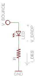 |
You will need to build a circuit consisting of an LED and resistor.
In order to protect your Beaglebone Blue and LED, be sure to choose the value of the current-limiting resistor so that the LED receives about 1.6mA of current. The supply voltage is 3.3V.
Extra Information
Version Control with Git
It's good to get into the habit of working with version control. This will pay dividends in the near future. Version control will let you easily save (and if necessary, roll back to) a version of code that works. It also enables multiple team members to work on code and merge changes.
Private course GitHub repositories will be handed out during checkpoint 0. If your team has not received your private repository yet, please email the TA (remembering to include to GitHub usernames of all team members).
You can also download the GitHub GUI client here on your personal computer. This should not require administrator permissions to run on the lab machines. SmartGIT works pretty nicely as well for non-commercial purposes: SmartGit.
SSH Setup
We will be connecting to the Beaglebone Blue over SSH. The lab machines already have SSH clients and an Ubuntu virtual machine installed. If you want to work on your own personal machine you can follow the instructions here or in step 2 of the getting started guide. Some operating systems will require driver installation.