EE192: Mechatronics Design Lab
Checkpoint 1
Introduction
This lab is designed to introduce you to the Freescale Kinetis L Freedom development board (KL25Z).
Useful documentation and pinout information can be found here:
Checkoff Requirements
Print “Hello World” to a serial terminal
Solder and blink and LED using a timer
Version Control with Git
It's good to get into the habit of working with version control. This will pay dividends in the near future. Version control will let you easily save (and if necessary, roll back to) a version of code that works. It also enables multiple team members to work on code and merge changes.
Private course GitHub repositories will be handed out during checkpoint 0. If your team has not received your private repository yet, please email the TA (remembering to include to GitHub usernames of all team members).
The starter code can be found on GitHub.
You can also download the GitHub GUI client here. This should not require administrator permissions to run on the lab machines.
Optional: Installing Keil Locally
If you want to use a laptop (instead of the lab machines) for development, this document (specifically sections 1-4) provides an overview of how to get things set up.
Installing the DFP (Device Family Pack)
The Device Family Pack provides programming support in uVision for a set of devices. Go to the ARMCM0 DFP page and download the Device Family Pack, then run it. By default, it should install itself into the uVision IDE. This should not require administrator permissions to install on the mab machines.
You may have to do this if you are using a fresh lab machine. The uVision IDE should complain if you don't have the DFP and try to load the code.
Keil uVision and Serial Communication
Let's write the classic “Hello World” program. The code to do this is straightforward and is provided in the starter code. This section will focus on Keil uVision and serial communication.
Download the starter code linked above and open ee192-sp14.uvproj in uVision.
Buildling: Go to Project > Build Target (or press F7).
Downloading Option 1: Attach the KL25Z to your computer via USB (shown below). It should show up as an external storage device. Copy/paste the file (repository root)/build/ee192-sp14_KL25Z.bin into that external storage device. Finally, press the reset button on the KL25Z.
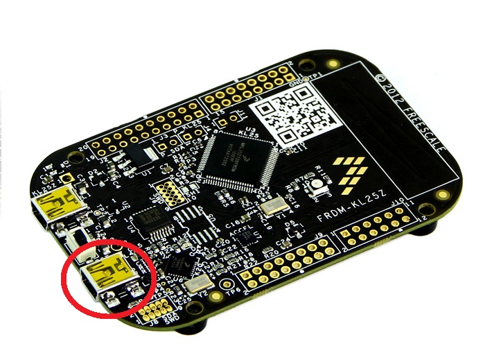 |
Use this USB port. |
Downloading Option 2: Attach the KL25Z to your computer via USB (shown above).
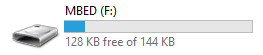 |
Make note of the drive letter (in this case “F”). |
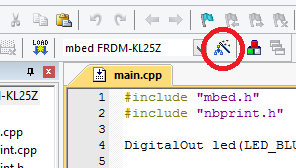 |
Click on “Target Options.”" |
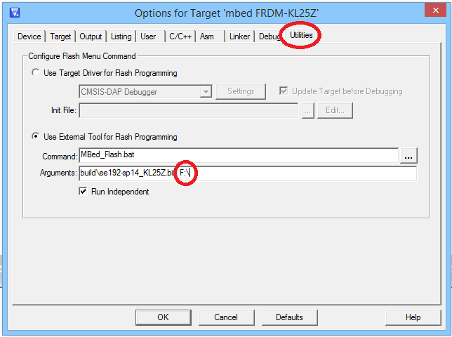 |
Ensure that the proper drive letter is specified. |
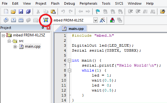 |
Press the yellow and blue “LOAD” button. |
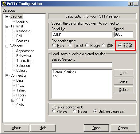
Serial communication using PuTTY: Select Connection type: Serial and ensure the correct COM port is selected. To check the COM port, open the Windows Device Manager (protip: Win+R, run devmgmt.msc), expand “Ports,” and look for “mbed Serial Port.”
Once you're connected, press the reset button on the KL25Z, and you should see it print “Hello World!”
 |
LED Blink
The next task is to make an LED blink at 1Hz, 75% duty cycle. This means that the LED is on 75% of the time and off 25% of the time.
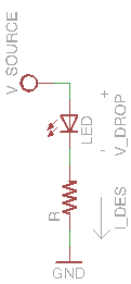 |
Do not use the built-in LED for this exercise. You will need to build a circuit consisting of an LED and resistor. Be sure to choose the value of the current-limiting resistor so that the LED receives about 1.6mA of current. The supply voltage is 3.3V. |
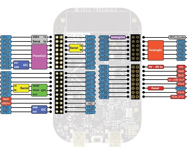 |
After you have finished your circuit, connect it to one of the pins on the KL25Z as well as one of the ground pins. In general, most pins can be configured to be used as a digital input or output. Update your code to reflect the pin you have chosen (such as PTA13 or PTE20). Remember that the LED is a diode and only works in one direction. Make sure the “flat side” of the LED is connected to ground. |
Extra: Fading LED using PWM
Due to properties of LEDs, they are normally either on or off. However, we can get them to fade using PWM, or Pulse Width Modulation. PWM allows for a digital approximation of an analog value by turning on and off the output very fast.
It's a good idea to get familiarized with PWM, as you will be using it for controlling your servo and motors later on.
Learn about the mbed PwmOut interface here.