EE192: Mechatronics Design Lab Spring 2013
lab 1
In lab 1, you will familiarize yourself with the Freescale Kinetis L Freedom development board (You are, however, free to choose any microcontroller platform you see fit to use, however, do note that help from the instructor/teaching assistant may be nonexistent).
getting started with freedom and codewarrior v10.3b
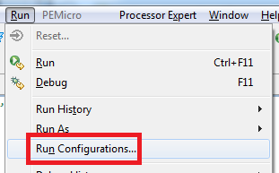 |
Ideally, your freedom board should already be configured properly as an OpenSDA device. (OpenSDA is a protocol that the freedom boards can use as a software USB debugger, i.e. virtual JTAG). To check whether your freedom board is recognized by CodeWarrior, open the CodeWarrior IDE and load the provided lab 1 project file. Navigate to the standard toolbar, and select “Run -> Run Configurations.” |
Following this, a “Run Configurations” window should pop up. On the left toolbar, make sure the file under CodeWarrior Download is selected. Under this, in the “Main” tab under the “Connection” field is an “Edit” function enabled. Click this, and a new window should pop up.
 |
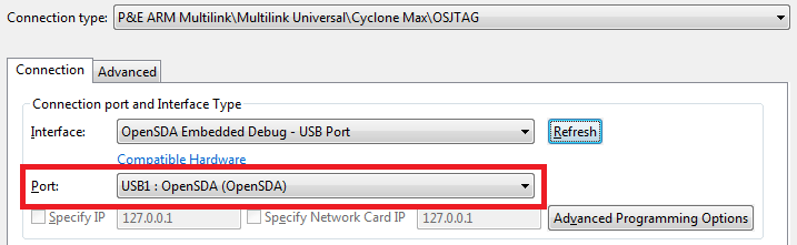
In the new window, under the “Connection” tab, specify the “Interface” as an “OpenSDA Embedded Debug - USB Port.” The “Port” should then be specified in the drop down box. It should read as USBx: OpenSDA (OpenSDA). where x is some number. After confirming this, your board should be connected and recognized.
 |
serial uart/usart hello world
Now we will write the classic hello world program. However, unlike personal computer C toolchains, we do not have a standard printf command to use. We are in luck, however. The ProcessorExpert software that is configured with CodeWarrior v10.3b allows us to use an API-driven development style, and will generate the proper functions so that we can use printf styled commands over serial communications.
The serial communications we are interested in is Universal (Synchronous) Asynchronous Receive Transmit, or UART (USART) for short. This logic is compatible with computer RS232 serial, however, since RS232 serial has been phased out due to technology (remember those old, fat screw connectors?), we will use what is known as a virtual RS232 serial port, which is a software emulation of RS232 of serial.
 |
To do this with our FRDM board, we must include the proper component in our ProcessorExpert file, which will then consequentially generate header and source files to use printf statements over serial. The component we are interested with is under “CPU External Devices”, labeled as a console IO component. The component enables the stido package commands, which includes the printf command. With the addition of this component, we can then generate the code from our ProcessorExpert file. Remember to configure it properly with consistent baud rates and other qualities! Also remember to allow ProcessorExpert to initialize the device, or alternatively you can initialize it in your code. |
One thing to watch out for is the UART device and pins chosen for the ConsoleIO device. Sometimes the ConsoleIO may need to be configured, sometimes not. To configure the ConsoleIO device, expand the component in your project space. There should be a SerialLDD subcomponent, which can be edited. To read over OpenSDA CDC Virtual Serial, the Serial device must be chosen as UART0 on pins PTA1/PTA2.
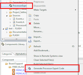
To generate code from the ProcessorExpert file, select the “Generate Processor Expert Code” from the right click context menu of the ProcessorExpert project file. This will proceed to generate header and source files.
From here, we notice there is a file named “ProcessorExpert.c” in our project. This is the file that ProcessorExpert generates with the main function. We can write our code here (marked by comments) using printf commands, such as shown below.
...
PE_low_level_init();
/*** End of Processor Expert internal initialization ***/

/* Write your code here */
printf("Hello World!\n");
...
After writing our code, we build the project using the “Build all” command found either on the toolbar as a button, or also under the “Build” menu. After building, we can then run the application using the “Run”, or alternatively use the “Debug” function for line-by-line debugging.
blinking led using timers
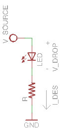 |
Next, we will do something with more physical meaning. We can use the freedom board to toggle the state of pins, which can have wide effects depending on application. For our lab, we will change the pin so that an externally attached light emitting diode (or LED for short) will blink on and off. First, we must create an LED circuit to which the freedom board will attach. LEDs are diodes, which mean that they have an exponential relationship between voltage across the terminals and current. They also are directional, so do note that they function in one orientation but not the other. However, in the real world, we can only put a finite amount of current through the device before the electronics are overloaded, so we need to limit the current through the LED somehow. For most applications, putting a resistor in series with an LED and then applying a constant voltage across the LED-resistor series network will generate a constant current to power our LED. We can select this resistor so that the current through the LED is limited to safe regions. |
We need to first establish the forward voltage drop of the LED, which is the minimum potential required by the LED to light up. We use the diode function of a multimeter (which should be at every lab station). This will give us a numerical value for the LED forward voltage drop. We can then use Kirchoff's current law to determine the current relationship with the resistance value.

From our choice of a desired current  , we can then compute a proper value of
  , the series resistance.
  is the source voltage, which is our pin that we will toggle between two states,
  and
and  . At , we can note that no current will pass through the circuit, so the LED will be off. At , we can see that the current will be nonzero, and thus depending on an appropriate value of , we can light the LED up.
After constructing this circuit, we now turn to CodeWarrior and ProcessorExpert. To set up a pin in which we can command to change states between and , we can add a component using ProcessorExpert called a I/O (which stands for input/output). We also include a timer component named “TimerUnit”. This is one application of a timer, which is a counter running at some configured frequency. Since we want to blink an LED at 1Hz, we require the LED to be on for 500ms, then off for the remaining 500ms to constitute a 1s period. Therefore, note that we require an interrupt to run every 500ms to switch the state of the LED pin. We need to configure our TimerUnit to do this.
After configuring this output, we then can generate and link the source and header files again from the context menu of the ProcessorExpert file. We can navigate to the header files dealing with this new I/O component, and then find the proper functions to set our pin high or low (or toggle, which we would be most ideal). We want to toggle the pin every time our timer interrupt calls. Luckily for us, the I/O we configured has a “Neg()” method, which negates the state (a NOT operation). We can use the corresponding interrupt service routine, or ISR, to perform an action every 500ms, in our case, a negation.
...
void BlinkingLEDTimer_OnCounterRestart(LDD_TUserData* UserDataPtr) {
	LED_Neg();
}
Note: In Processor Expert, interrupts are sometimes referred to as “Events”. The interrupt service routines can be found in the “Events.c” file.
extra: fading led using pwm
If you have ever noticed things such as the MacBook power light fading in and out, or variable color LEDs, this is typically done through PWM. PWM allows for an digital approximation of an analog value by abusing bandwidth properties. PWM on microcontrollers are implemented with timers, however, in ProcessorExpert, this has already been done as a component.
extra: Non-printf serial communication
Typically, the printf implementation uses a relatively large amount of memory to implement. We can bypass this by writing our own serial communications using the logic device components in ProcessorExport dealing with UART communication.
checkoff points
Demonstrate a working serial communication through terminal.
Demonstrate a blinking LED at 1 Hz (that is, 500ms ON and 500ms OFF).