Checkoff requirements
-
Drop onto track from a height of 30.5 cm (1 ft)
-
Travel around the figure eight track at 1m/s for 10 seconds (approximately one lap)
-
Lines placed 1m apart will be used to verify velocity
PID controller notes
-
PID Without a PhD
This article may be useful for a practical implementation of a PID control loop on a microcontroller. It talks about integrator windup and tips for tuning. -
How to build a fixed-point PI controller that just works: Part 1
This article features more code subtleties… and may be worth following to see if Part 2 comes up soon.
Edge-triggered interrupts
This is a brief note on implementing edge-triggered interrupts on the ADuC7020. This microcontroller only has level-sensitive interrupts which are triggered by a HIGH value. If you hook up an encoder to the level-sensitive interrupt pin, you will have to make sure in software that you don.t double-count any edges.
One alternative is to build the edge-detection logic in the ADuC.s PLA (programmable logic array). The PLA is a unit with logic gates and flip-flops which are reconfigured by setting some registers. It is documented on page 70 of the datasheet.
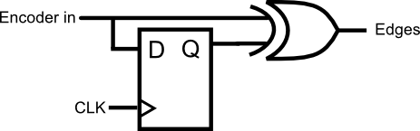
If I have a delayed copy of the input, then I can XOR it with the current input. If the two values are different, then there must have been a falling OR a rising edge. (Replacing the XOR with different gates will detect only rising / only falling edges.)

I can use a D-type flip-flop to implement the delay:
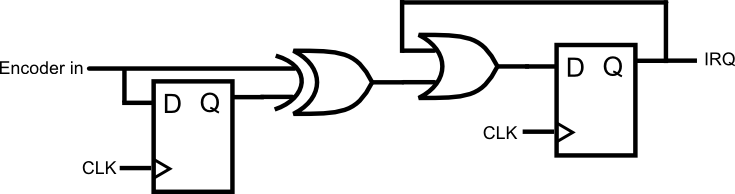
Now I have a circuit that detects edges. However the processor needs the IRQ line to be HIGH for >50 cycles in order to trigger the level-sensitive interrupt. Therefore I use another flip-flop to latch the HIGH value.
Finally, I need a way of clearing the interrupt. I can add an AND gate to implement a reset line.
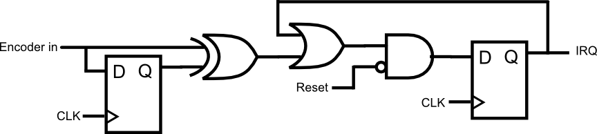
Here is an implementation of the PLA logic. It uses P1.4 as the input, PLA DIN0 as the reset, and PLA IRQ0 as the interrupt. Open it with the PLATOOL to edit it and generate the PLA configuration code.
Back-EMF sensing
An alternative to encoders is to measure the back-emf generated by the motor to infer its speed.
If anyone would like to contribute an application note (either original or a link) I would appreciate it :)