Goals
- Learn how to use the remaining essential parts of logisim. In particular, splitters (split/rejoin subsets of bits on a bus) and the Enable bits on registers.
- Get some hands-on experience with pipelining.
Reading
- P&H 4.5, 4.6
- Refer to the Logisim Website or last week's lab for a refresher on Logisim.
Setup
Copy the contents of ~cs61c/labs/10 to a suitable location in your home directory.
Note: As there is no official lab on Thursday, you essentially have 2 lab periods to do this lab (though don't forget about hw5 and proj2-2). This lab must be completed and checked off within the first 10 minutes of your lab on Tuesday 8/6/2013.
Exercises
Exercise 1: Splitters
To demonstrate the use of splitters you will construct a circuit that manipulates an 8-bit number.
- Open a new file and save it as ex1.circ. Complete the remaining steps in the "main" part of this circuit.
- Add an 8-bit input pin to your circuit and label it.
- Add a 1-bit output pin labeled "Out1" and an 8-bit output pin labeled "Out2" to your circuit.
- Go to the Wiring folder and select the Splitter circuit. This circuit will take a wire and split it into a smaller set of wires. Conversely, it can also take many sets of wires and combine them into a larger bus.
- Before you place your circuit, change the "Bit Width In" property (bus width) to 8, and "Fan Out" property (# of branches) to 3.
If you move your cursor over the schematic, your cursor should look as follows:

- Now, select which bits to send out to which part of your fan. The least significant bit is bit 0 and the most significant bit is bit 7. CHANGE bits 1, 2, and 6 to be coming out on fan arm 1 (the middle one) while leaving the rest on their default fan arms.
- Once you configure your splitter, you can place your splitter into your circuit.
- Attach a 2-input AND gate to fan arms 0 and 2 and route the output of the AND gate to Out1.
- Now we want Out2 to be the negative sign and magnitude value of the input. The combinational logic should be straight-forward.
- We will need another splitter to recombine the fans into a single 8-bit bus. Place another splitter with the proper properties (Bit Width In: 8, Fan Out: 3, correct fan widths). Play with the Facing and Appearance properties to make your final circuit as clean-looking as possible.
In general, splitters do not need to come in pairs and can be used to arbitrarily create/combine buses of varying widths. They can even be used to reduce a bus width (set the bits you don't want to fan arm "None")! When connecting buses to splitters, the individual bits will be ordered automatically as normal (higher bit numbers mean more significant -- more to the left).
Check-off
- Show ex1.circ to your TA.
- Assuming 2's complement representation, what inputs will produce Out1 = 1? You should be able to describe this set qualitatively in four words: "all _____, _____ numbers".
Exercise 2: Rotate Right
With your knowledge of splitters and your knowledge and experience with multiplexers from the last lab, you are ready to implement a non-trivial combinational (no registers allowed) logic block: rotr ("Rotate Right"). The idea is that rotr A,B will "rotate" the bit pattern of input A to the right by B bitsi, placing any bits that shift off the bottom end (LSB) onto the top end (MSB). As an example:
B = 0b0101 (5 in decimal)
A = 0b1011010101110011
then rotr A,B =  0b1001110110101011
Notice that the rightmost 5 bits were rotated off the right end of the value and back onto the left end. You must implement a subcircuit named "rotr" with the following inputs:
- A, 16 bits, the input to be rotated
- B, 4 bits, the rotation amount (Why 4 bits?)
The output should be A rotated right by B bit positions, as outlined above. You are NOT allowed to use Logisim shifters in your solution, though all other combinational logic (MUXes, constants, gates, adders, etc.) is allowed. Show off your rotr subcircuit in the main subcircuit and save your file as rotr.circ.
Hint: Before you start wiring, you should think very carefully about how you might decompose this problem into smaller ones and join them together. You should feel very free to use subcircuits when implementing rotr. If you don't, expect to regret it (very messy/tedious wiring). Try to use what you learned about splitters in Exercise 1 to keep your wiring as neat as possible.
Tip: If your wiring from a large splitter is getting messy, sometimes chaining splitters can keep things more localized and cleaner. For example, a 1 to 16 split can be achieved by a fan out of 4 connected to 4 more splitters of fan out 4. (this goes for your homework, too)
Check-off
- Show your TA your rotr circuit and verify that it works.
Exercise 3: Fibonacci Numbers
So far we have built circuits that are either 1) purely combinational and require no clock or 2) have memory but run infinitely. In this exercise, we want to build a circuit that will compute the Nth Fibonacci number. As a quick review the Fibonacci numbers are defined by F0 = 0, F1 = 1, and Fi = Fi-1 + Fi-2.
- Start with just the infinite Fibonacci computation. Hopefully this should be pretty intuitive based on previous exercises that you have done before. How many registers do you need? What arithmetic blocks do you need? Where should the output be attached? Make sure you figure out a way to properly initialize the registers for the computation to work.
- Your subcircuit will compute up to the 15th Fibonacci number and we will assume our input N > 0 is an unsigned number. How many input bits do you need and how many output bits do you need to represent the 15th Fibonacci number?
- Now to prevent the circuit from computing the Fibonacci numbers to infinity, we will make use of the Enable bit (lower left) on registers. When unset or pulled high, the registers will continue to load their inputs on the rising edge of the CLK. If Enabled is pulled low, then the registers will NOT load their inputs. We need to create a signal that will properly go low when we want the circuit to stop computing Fibonacci numbers.
- Create an additional part of the circuit that halts the original circuit after N computations. For this exercise you may find the following blocks useful: Counter (Memory), Comparator (Arithmetic), and Probe (Wiring). Make sure that it properly stops on the Nth Fibonacci number (watch for off-by-one errors) and that it actually stays there (run it for at least 20 clock cycles).
Your output should be in binary, but you can use a Probe to display the value in decimal. Hint: Make sure you check the attributes/properties of any counter and comparator you use.
Extra for Experts: With proper register initialization, you can get this circuit fib15 to work properly for N > 0. But register initialization is annoying and must be repeated every time you reset your circuit. With a clever addition, you can get this fib15 to work for N >= 0 without the need for register initialization (Hint: it involves a MUX).
Check-off
- Explain your fib15 circuit to your TA and verify that for N = 15 it will return Out = 610 indefinitely after some time.
Exercise 4: Pipelining
This next exercise will get you some hands-on practice with pipelining. Before you get started, it is highly recommended that you remind yourself what the following terms mean, how they are defined, and how they are related:
- critical path, maximum delay, minimum clock period, maximum clock frequency
Consider the following 2-input FSM. Its next state and output is computed by multiplying the inputs and adding it to the current state. Note that the Input 2 and Input 3 registers in the below diagram are simply for visualization purposes (and to clarify the elements you need to include in your clock rate calculation below). In pipeline.circ, you'll notice that the FSM is actually fed values by a ROM block in the "main" circuit.
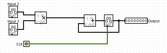
Component specs:
- propogation delay of adder = 50 ns
- propogation delay of multiplier = 55 ns
- clk-to-q delay of a register = 5 ns (and hold time less than this)
- negligible register setup time (~0 ns)
As shown in the above diagram, assume that both inputs come from clocked registers (i.e. their values update a clk-to-q delay after a clock trigger). Calculate the maximum clock rate at which this circuit can operate.
Now pipeline it! We want to improve the performance of this circuit, and let it operate at a higher clock rate. To do so, we will divide up the multiplication and addition into two different pipeline stages; in the first pipeline stage, we will perform the multiplication of the two inputs. In the second pipeline stage, we will add the product to the state.
Our definition of "correctness" will be simple: we will consider the sequence of outputs from this circuit "correct" iff it corresponds to the sequence of outputs the non-pipelined version would emit, potentially with some leading zeros. For example, if for some sequence of inputs the non-pipelined version emits [3,5,1,2,4, ...], a correct circuit might emit the sequence of outputs [0,3,5,1,2,4, ...] for that same sequence of inputs.
For your convenience and to help standardize check-offs, we are providing a starting point in the files pipeline.circ and ROMdata. In pipeline.circ, the subcircuit Non-pipelined is set up exactly as the figure above. The main circuit is set up to produce the output sequence [3,5,1,2,4,-1,0,0,...] on the non-pipelined version of this circuit. It is also a handy example of how to use memory from a file. The ROM block should be initialized to the proper data, but if it is zero-ed out, right-click it and choose "Load image..." and select ROMdata.
Note that we need a register to hold the intermediate value of the computation between pipeline stages. This is a general theme with pipelines.
- Complete the sub-circuit Pipelined. You will need to add a register to divide the multiplication and addition into separate pipeline stages.
- Calculate the maximum clock rate for the pipelined version of the circuit.
- When we talked about pipelining in lecture, we discussed that if a computation depends on the output of a previous computation, it's difficult to pipeline them and we often need to insert a pipeline "bubble" (or several) to ensure that the output of the first computation is ready to be an input to the second. Explain why inserting such "bubbles" is unnecessary for this particular circuit.
Check-off
- For both versions of this circuit (non-pipelined and pipelined), show your TA the circuit, explain where the critical path is, then explain your calculation of the maximum clock rate.
- Go to the main circuit of pipeline.circ and verify correct behavior of your pipelined circuit. Why is there a delay in the output compared to the non-pipelined version?
- Explain to your TA why bubbles are unecessary in this circuit.