Goals
There are two parts to this lab. In the first part, you will be learning how to use the remaining essential parts of logisim, in particular, splitters to take a subset of bits on a wire, and to rejoin them. In the second part, you will gain some hands-on experience with pipelining.
Reading
P&H 4.5, 4.6
Refer to the Logisim Website
or last week's lab for a refresher on Logisim.
Setup
For part A, start all Logisim circuits from scratch. Feel free to do each exercise as separate sub-circuits in the same Logisim file.
For part B, you can find a starter circuit and data file in ~cs61c/labs/10 or using the links provided in the problem description.
Note: As there is no official lab on Thursday, you essentially have 2 lab periods to do this lab!
Exercises
The following exercises will introduce you to more advanced techniques/concepts in Logisim.
Exercise A.1: Splitters
This is the last essential tool you will need in this class. To demonstrate its use you will construct a circuit that manipulates an 8-bit number.- Create a new subcircuit and name it "Ex1".
- Add an 8-bit input pin to your circuit and label it.
- Add a 1-bit output pin labeled "Out1" and an 8-bit output pin labeled "Out2" to your circuit.
- Go to the Wiring folder and select the Splitter circuit. This circuit will take a wire and split it into a smaller set of wires. Conversely, it can also take many sets of wires and combine them into a larger bus.
- Before you place your circuit, change the "Bit Width In" property (bus width) to 8, and "Fan Out" property (# of branches) to 3. If you move your cursor over the schematic, your cursor should look as follows:

- Now, select which bits to send out to which part of your fan. The least significant bit is bit 0 and the most significant bit is bit 7. Change bits 1, 2, and 6 to be coming out on fan arm 1 (the middle one). FYI: the "None" option means that the selected bit will not come out on ANY of the fan arms.
- Once you configure your splitter, you can place your splitter into your circuit.
- Attach a 2-input AND gate to fan arms 0 and 2 and route the output of the AND gate to Out1.
- Now we want Out2 to be the negative sign and magnitude value of the input. The combinational logic should be straight-forward.
- We will need another splitter to recombine the fans into a single 8-bit bus. Place another splitter with the proper properties (Bit Width In: 8, Fan Out: 3, correct fan widths). Play with the Facing and Appearance properties to make your final circuit as clean-looking as possible.
Checkoff
- Show your Ex1 circuit to your TA.
- Assuming 2's complement representation, what inputs will produce Out1 = 1?
Exercise A.2: Rotate Right
With your knowledge of splitters and your knowledge and experience with multiplexers from the last lab, you are ready to implement a non-trivial combinational logic block:rotr, which stands for "Rotate Right". The idea is that rotr A,B will "rotate" the bit pattern of input A to the right by B bits. So, if A were 0b1011010101110011 and B were 0b0101 (5 in decimal), the output of the block would be 0b1001110110101011. Notice that the rightmost 5 bits were rotated off the right end of the value and back onto the left end. In RTL, the operation would be something like "R = A >> B | A << (16 - B)".
You must implement a subcircuit named "rotr" with the following inputs:
- A, 16 bits, the input to be rotated
- B, 4 bits, the rotation amount (Why 4 bits?)
rotr subcircuit in the main subcircuit.
Hint: Before you start wiring, you should think veeeery carefully about how you might decompose this problem into smaller ones and join them together. You should feel very free to use subcircuits when implementing rotr. If you don't, expect to regret it.
Tip: If your wiring from a large splitter is getting messy, sometimes chaining splitters can keep things more localized and cleaner. For example, a 1 to 16 split can be achieved by a fan out of 4 connected to 4 more splitters of fan out 4. (this goes for your homework, too)
Checkoff
- Show your TA your rotr circuit and verify that it works.
Exercise A.3: Fibonacci Numbers
So far we have built circuits that are either 1) purely combinational and require no clock or 2) have memory but run infinitely. In this exercise, we want to build a circuit that will compute the Nth Fibonacci number. As a quick review the Fibonacci numbers are defined by F0 = 0, F1 = 1, and Fi = Fi-1 + Fi-2.
- Start with just the infinite Fibonacci computation. Hopefully this should be pretty intuitive based on previous exercises that you have done before. How many registers do you need? What arithmetic blocks do you need? Where should the output be attached? Make sure you figure out a way to properly initialize the registers for the computation to work.
- Your sub-circuit will compute up to the 15th Fibonacci number and we will assume our input N > 0 is an unsigned number. How many input bits do you need and how many output bits do you need to represent the 15th Fibonacci number?
- Now to prevent the circuit from computing the Fibonacci numbers to infinity, we will make use of the Enable bit (lower left) on registers. When unset or pulled high, the registers will continue to load their inputs on the rising edge of the CLK. If Enabled is pulled low, then the registers will NOT load their inputs. We need to create a signal that will properly go low when we want the circuit to stop computing Fibonacci numbers.
- Create an additional part of the circuit that halts the original circuit after N computations. For this exercise you may find the following blocks useful: Counter (Memory), Comparator (Arithmetic), and Probe (Wiring). Make sure that it properly stops on the Nth Fibonacci number (watch for off-by-one errors) and that it actually stays there (run it for at least 20 clock cycles).
Bonus: With proper register initialization, you can get this circuit fib15 to work properly for N > 0. But register initialization is annoying and must be repeated every time you reset your circuit. With a clever addition, you can get this fib15 to work for N >= 0 without the need for register initialization (Hint: it involves a MUX).
Checkoff
- Show your TA your fib15 circuit and verify that for N = 15 after some time it will return Out = 610 indefinitely.
Part (B): Pipelining
This next exercise will get you some hands-on practice with pipelining. Assume that on power-on, registers initially contain zeros.
Consider the following 2-input FSM. Its next state and output is computed by multiplying the inputs and adding it to the current state.
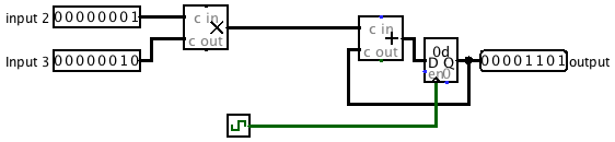
Say the propogation delay of a adder block is 50ns, the propogation delay of a multiplication block is 50 ns, and the clk-to-q delay of a register is 5ns. Calculate the maximum clock rate at which this circuit can operate. Assume that the register setup time is negligible, and that both inputs come from clocked registers that receive their data from an outside source.
Checkoff
- Show your TA the calculations you performed to find the maximum clock rate (non-pipelined).
We want to improve the performance of this circuit, and let it operate at a higher clock rate. To do so, we will divide up the multiplication and addition into two different pipeline stages; in the first pipeline stage, we will perform the multiplication of the two inputs. In the second pipeline stage, we will add the product to the state.
Our definition of "correctness" will be simple: we will consider the sequence of outputs from this circuit "correct" iff it corresponds to the sequence of outputs the non-pipelined version would emit, potentially with some leading zeros. For example, if for some sequence of inputs the non-pipelined version emits [3,5,1,2,4, ...], a correct circuit might emit the sequence of outputs [0,3,5,1,2,4, ...] for that same sequence of inputs.
For your convenience and to help standardize check-offs, we are providing a starting point in the files pipeline.circ and ROMdata (use the links or copy from ~cs61c/labs/10/). In pipeline.circ, the sub-circuit Non-pipelined is set up exactly as the figure above. The main circuit is set up to produce the output sequence [3,5,1,2,4,-1,0,0,...] on the non-pipelined version of this circuit. It is also a handy example of how to use memory from a file. The ROM block should be initialized to the proper data, but if it is zero-ed out, right-click it and choose "Load image..." and select ROMdata.
Note that we need a register to hold the intermediate value of the computation between pipeline stages. This is a general theme with pipelines.
- Complete the sub-circuit Pipelined. You will need to add a register to divide the multiplication and addition into separate pipeline stages.
- Calculate the maximum clock rate for the pipelined version of the circuit.
- When we talked about pipelining in lecture, we discussed that if a computation depends on the output of a previous computation, it's difficult to pipeline them and we often need to insert a pipeline "bubble" (or several) to ensure that the output of the first computation is ready to be an input to the second. Explain why inserting such "bubbles" is unnecessary for this particular circuit.
Checkoff
- Show your TA the completed, pipelined circuit.
- Show your TA the calculations you performed to find the maximum clock rate (pipelined).
- Explain to your TA why bubbles are unecessary in this circuit.