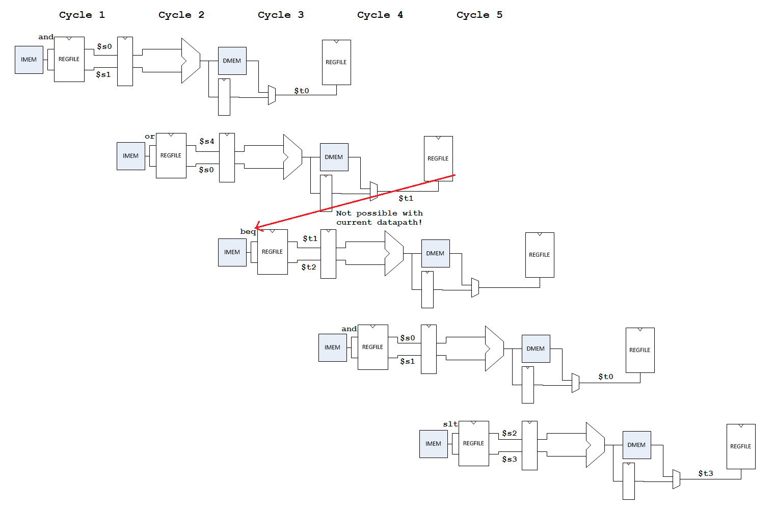
If instructions at 0x24 and 0x28 were also executed immediately prior to the instruction at 0x20, the following sequence of instructions would be executed:
and $t0, $s0, $s1
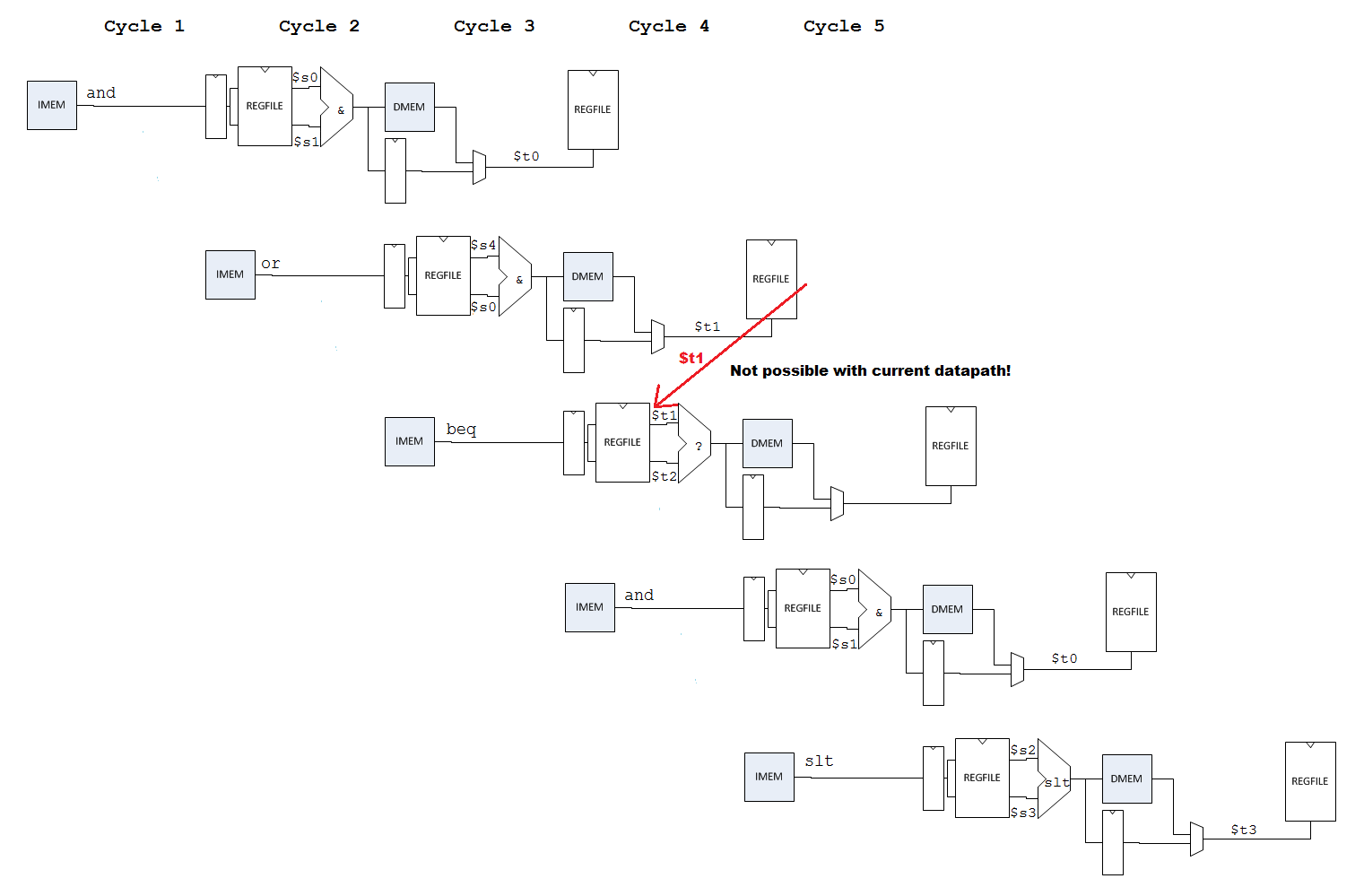
or $t1, $s4, $s0
beq $t1, $t2, 40
and $t0, $s0, $s1
slt $t3, $s2, $s3
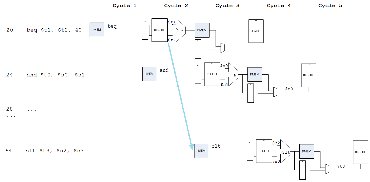
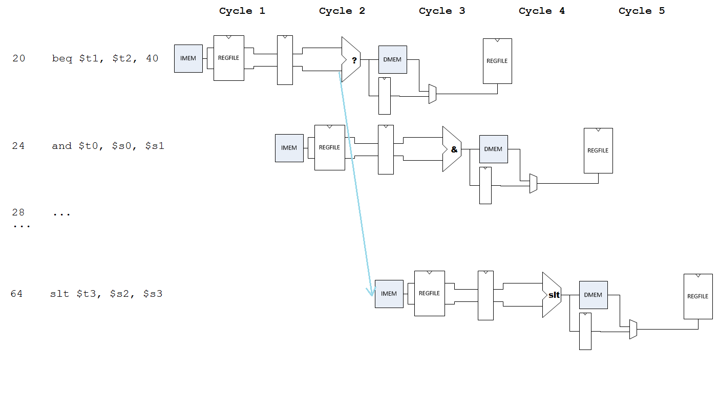
As before, the value of $t1 generated by the `or' is not ready when the value of $t1 is read from the register file by the `beq.' This conflict is actually changed; the value of $t1 from the `or' is now still written back on the positive edge of the clock following the cycle when the `beq' is in the execute stage; however, the `beq' actually reads $t1 in the decode stage, meaning it could even have an unresolved RAW hazard if an instruction that starts executing two cycles earlier modifies one of its operands. This conflict is illustrated in the next figure.
Figure
Figure 5: Unresolved RAW hazard
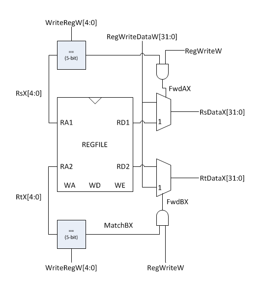
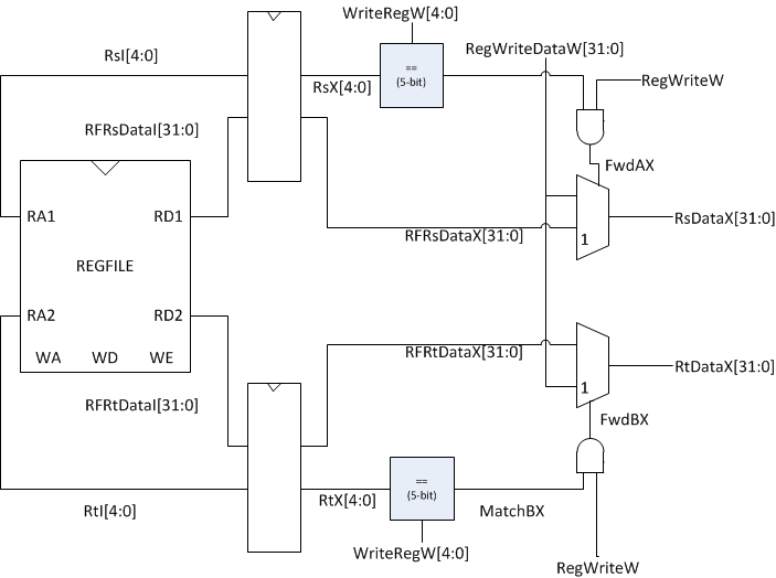
This cannot be fixed by forwarding to the outputs of the regfile, as the `beq' leaves the decode stage (where the regfile fetch occurs) before the `or' is in the writeback stage. However, the forwarding multiplexers can be placed after the pipelining registers that hold the register addresses and data in the execute stage.
Figure
Figure 6: Forwarding to address RAW hazards
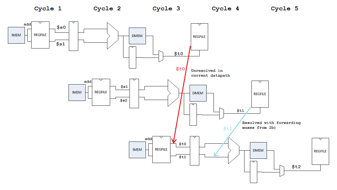
This does not resolve all the potential RAW hazards; although the sequence of instructions given in the problem will now execute with no stalling, the potential still exists for an instruction reading a register two instructions after an instruction that modifies it, which will result in an unresolved RAW hazard in this design.
Considering the instruction sequence below:
add $t0, $s0, $s1
add $t1, $s1, $s2
add $t2, $t0, $t1
The resolved and unresolved RAW hazards are shown in the pipeline diagram below.
Figure
Figure 7: Resolved & unresolved RAW hazards